
Guide to building the Tastic RFID Thief
The Tastic RFID Thief has been around since late 2013, and since I've had a tremendous amount of requests asking how to build it, I thought that this blog post would be of justice to the tastic.
About the Tastic RFID Thief
The Tastic RFID Thief was introduced by the company Bishop Fox - https://resources.bishopfox.com/resources/tools/rfid-hacking/attack-tools/ through a series of Defcon and Blackhat videos across mid-late 2013. Bishop Fox describe the Tastic silent, long-range RFID reader that can steal the proximity badge information from an unsuspecting employee as they physically walk near this concealed device.
I built my first Tastic RFID Thief in February 2014, with no experience in electronics, and as a total challenge given to me by my boss at the time. It was an overall fun experience however, and I'm grateful that I was able to push myself. So, to all those who want to build one, but don't quite have the experience to do so, my advice is just go for it. The Tastic RFID you see in this post, is the second that I have built for a security consultancy company in Sydney.
This guide assumes that you are doing constant testing of the circuit along the way. Whilst this guide itself isn't so detailed and bullet proof, it definitely will act as a great reference and tutorial towards building the Tastic.
Getting Started
1. Getting your parts in order
Bishop Fox conveniently provide a downloadable list of parts, which you can find here. Most parts are necessary for the production of the tastic, however the following three parts are not really needed:
You can mount the board yourself with some tape/hackiness:
- Adafruit - Board Edge Mounting Kit - Pack of 4 ID 1116 (~$3) http://www.adafruit.com/products/1116
This is for showing off/aesthetic purposes only:
- Two Wire Display Stand; Set of 2 6A - Black (~$9) http://www.amazon.com/gp/product/B000RO6CEC/
Official HID MaxiProx 5375AGN00's come with a screw to tighten the lid by default:
- Single thumbscrew in front to hold cover on
Nylon 6/6 Thumb Screw, Knurled Head, #6-32, 3/4" Length (ASIN: B000FN2ADW)
http://www.amazon.com/gp/product/B000FN2ADW
Since the above isn't stated in the parts list, I thought I would just make it clear to new comers that those parts are not essential.
Additionally, the project will require having access to the following equipment:
- Soldering Iron w/ solder
- Some sort of clamp to hold anything which needs to be soldered
- Header pins, rainbow cable
Last, but not least, Bishop Fox have kindly provided the PCB design/schematics needed for this project. They are freely available and can be found here.
You can get such a Fritzing PCB printed out via:
http://fab.fritzing.org/fritzing-fab or http://www.4pcb.com
2. Connecting up the PCB
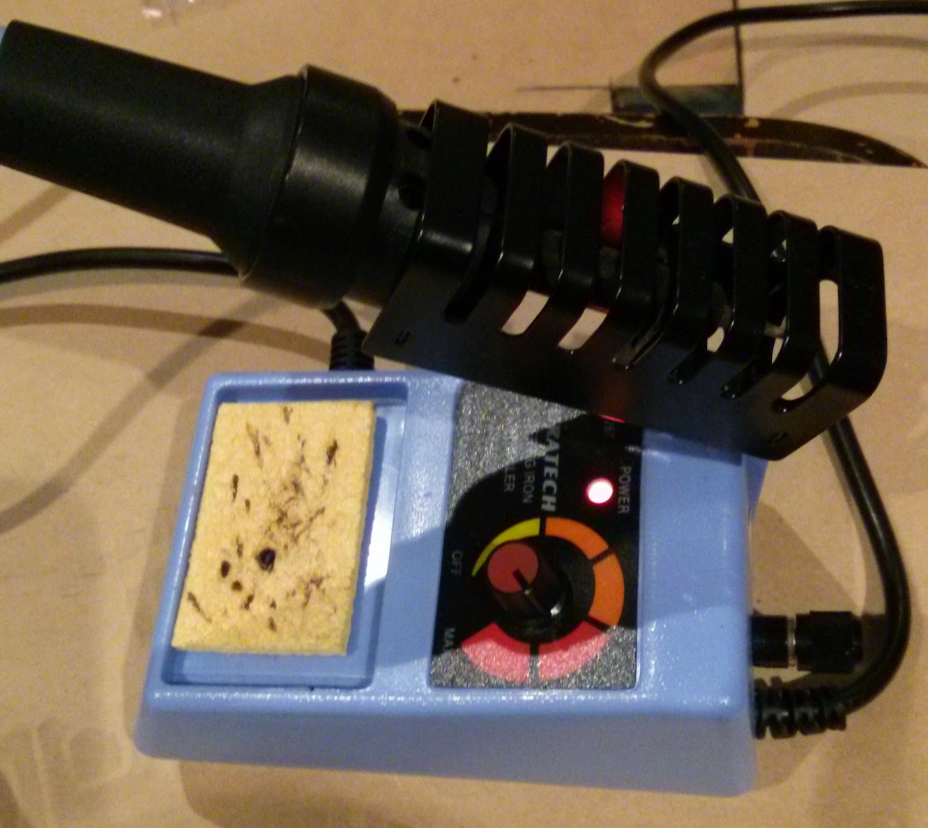
In order to connect up the PCB, you'll need to fire up your soldering iron to around 400°C and wait some time to ensure that it is hot, and ready to go.
While the solder is warming up, simply place the Ardiuno Nano onto the PCB, fitting it in where outlined:
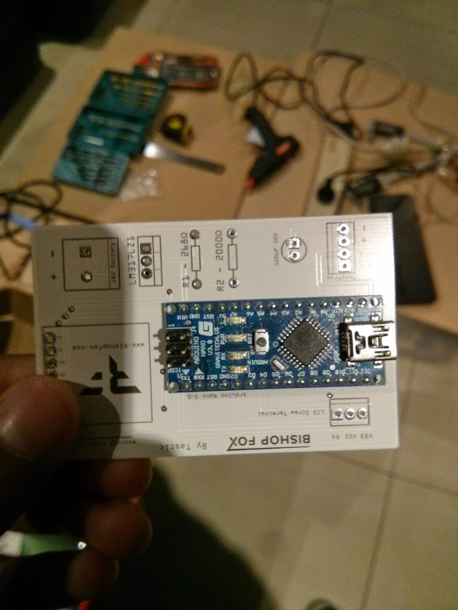
When in place, it should look something like this:
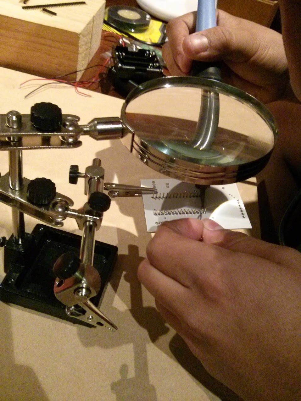
By either using a clamp, or something which can hold the arduino, as well as PCB in place upside down, solder the arduino on:
The end result should look like this:
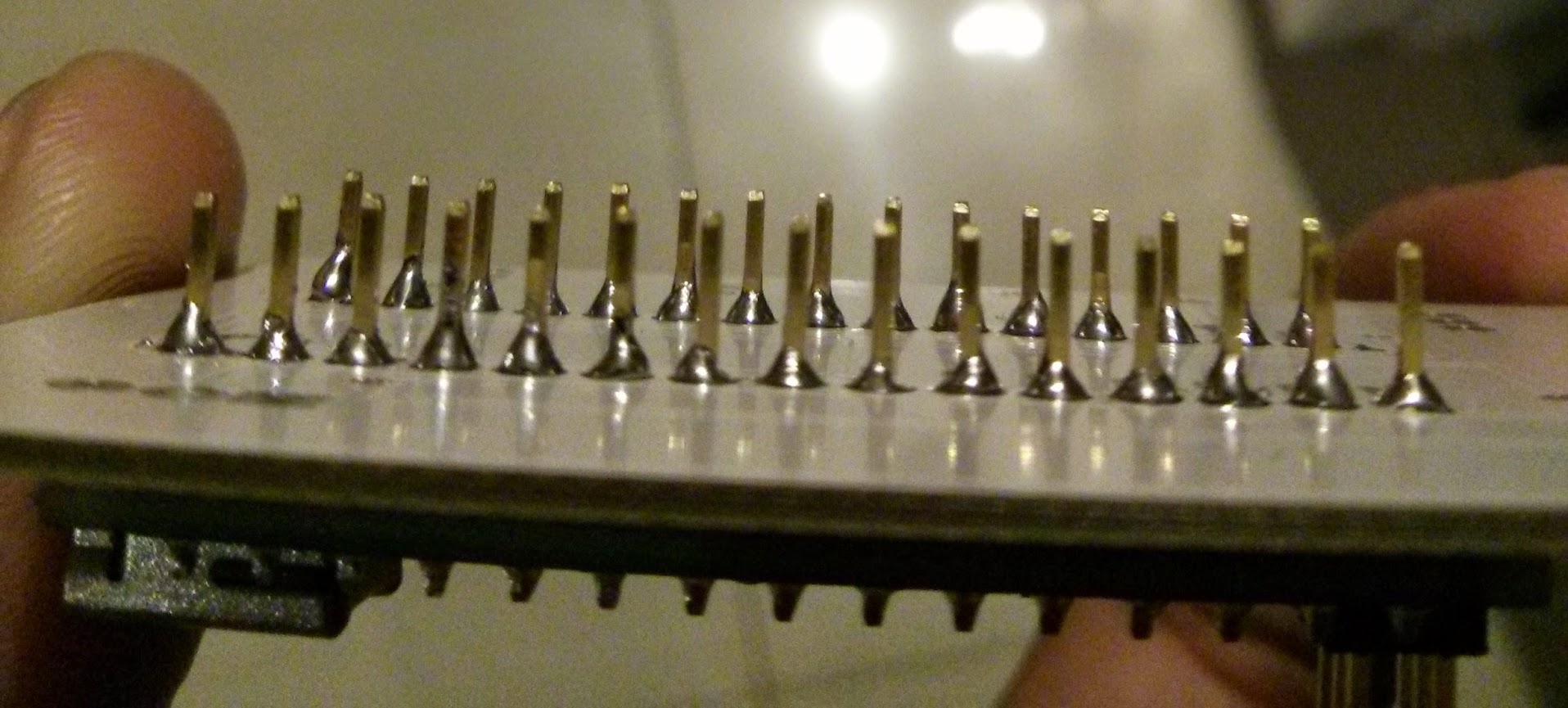
Since the general gist of soldering things onto the PCB has been established, just continue adding all the other parts via soldering onto the PCB where indicated on the PCB. Here's how my PCB turned out, which should be good guidance of how to set everything up.

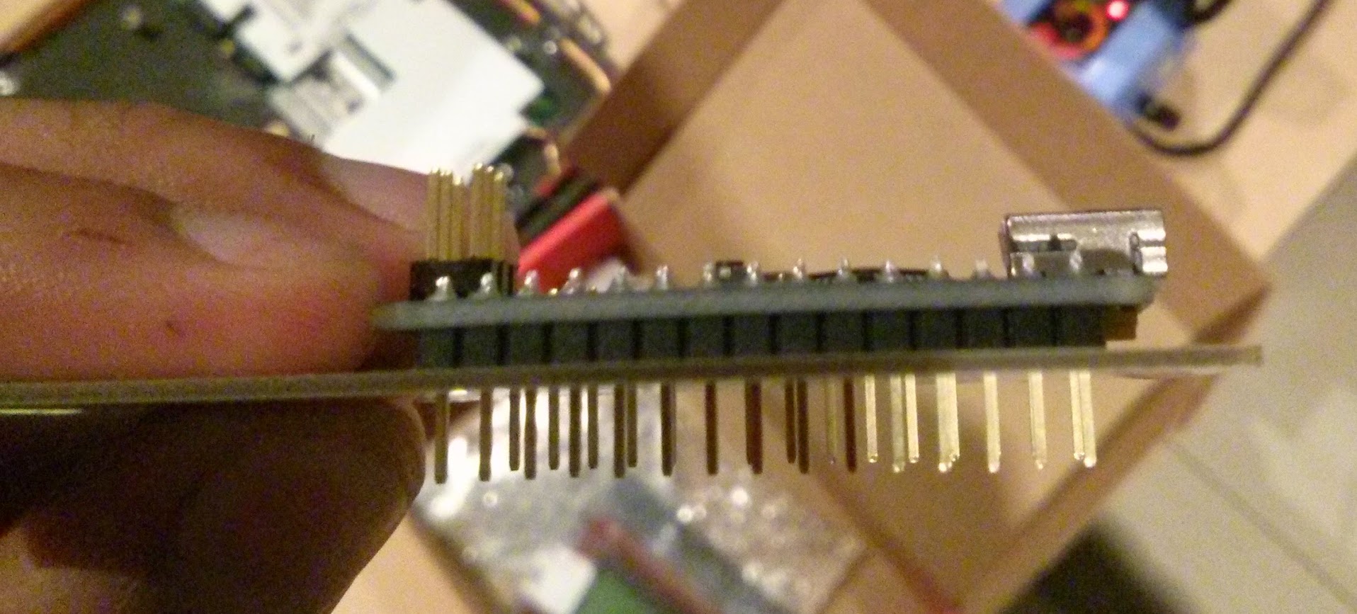
Clip anything from the bottom of the PCB if it is too long, e.g. pins from the arduino and the legs of the resistors, capacitors and voltage regulators.
Note: For the Maxiprox connection pins for the PCB, you can see how my PCB contains header pins instead of a direct connection. This allows for the PCB to be moved freely, right until we make the final connection.
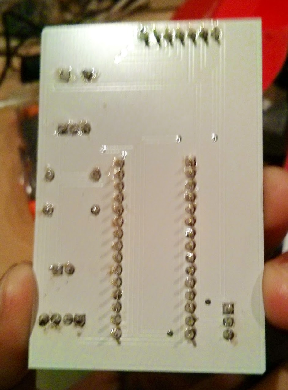
Congratulations, your PCB now has all the parts needed, attached. We can now continue with the assembly of the LCD screen.
Here is how the PCB should look from the bottom (sorry for the blurriness!):
3. Assembling the LCD Screen
The LCD screen, in my opinion is largely not required. Perhaps for demonstration and debugging purposes it can be quite useful, however in a real life penetration test, it's unlikely that once you steal a persons RFID information, you'll quickly check your Tastic RFID Thief to see the number pop up on the LCD screen momentarily.
However, I did document it for everyone.
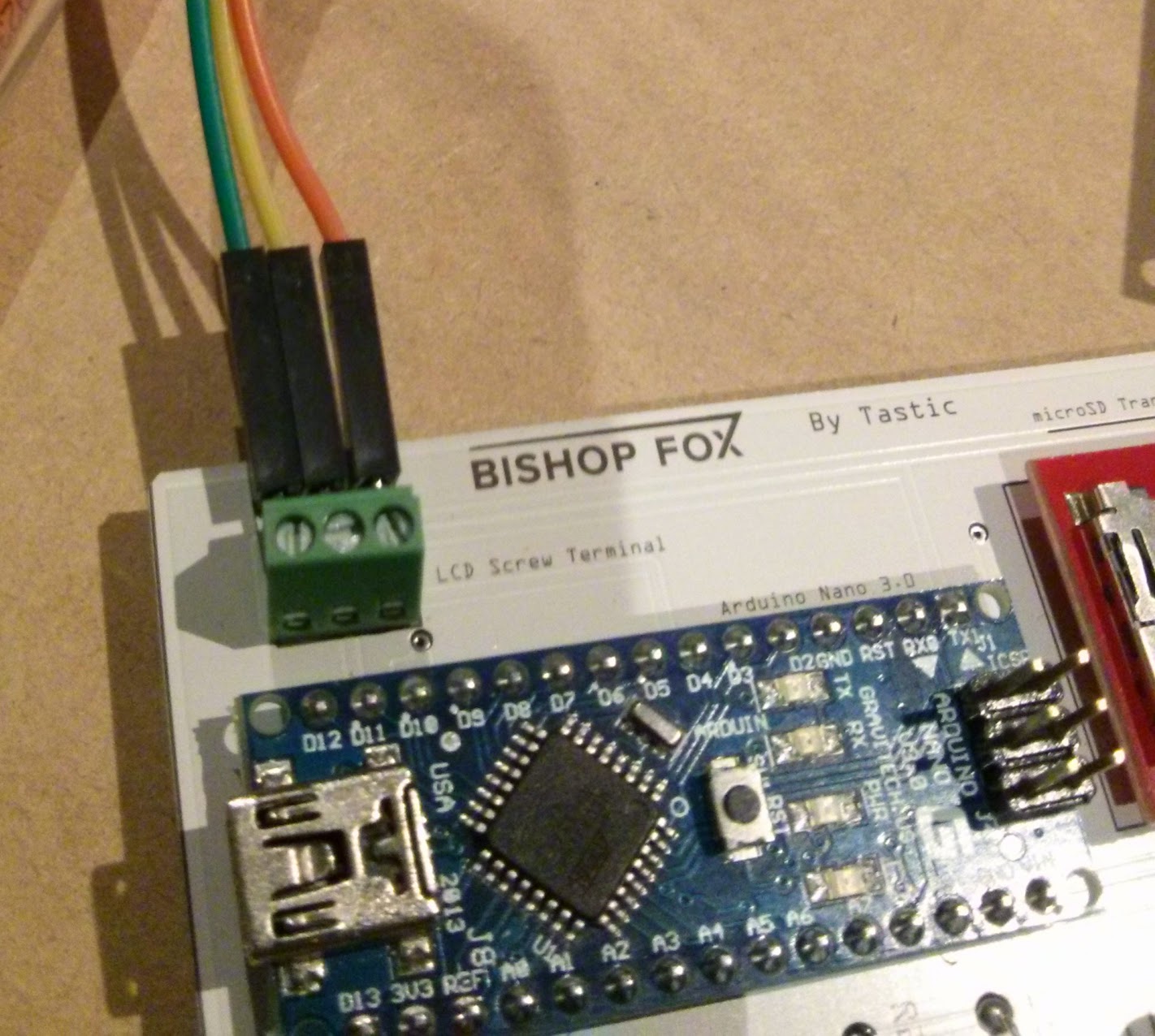
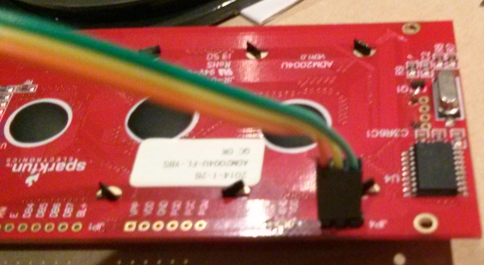
Since header pins are all round useful, add some header pins to the RX, GND and VDD spots on the LCD board. Solder these header pins on, like seen in the image below:
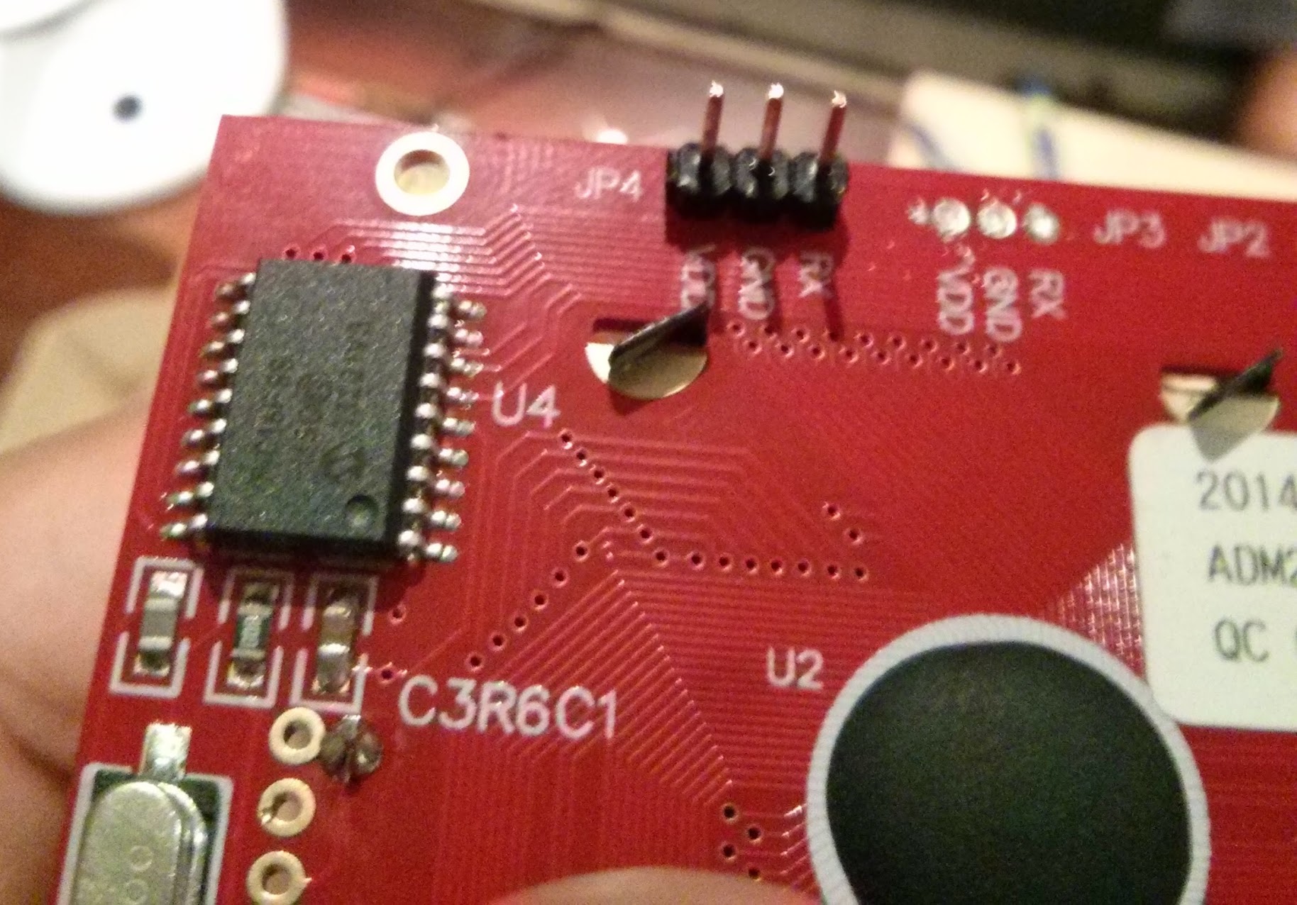
These three pins will join accordingly to the 3 pin terminal block on the PCB. Keep track of the colours I used for the connection (green = VDD, yellow = GND, orange = RX).
4. Preparing the Batteries
In this build of the Tastic RFID Thief, instead of the suggested 2 x 6 battery case solution, I was forced to instead use 3 x 4 battery case solution.
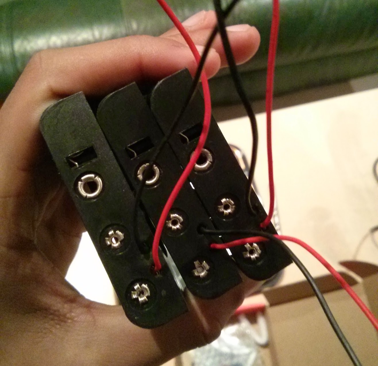
Basically, connect the battery packs up like the image below (Note: Don't solder all the connections until you're happy with the arrangement and the switch has been added):
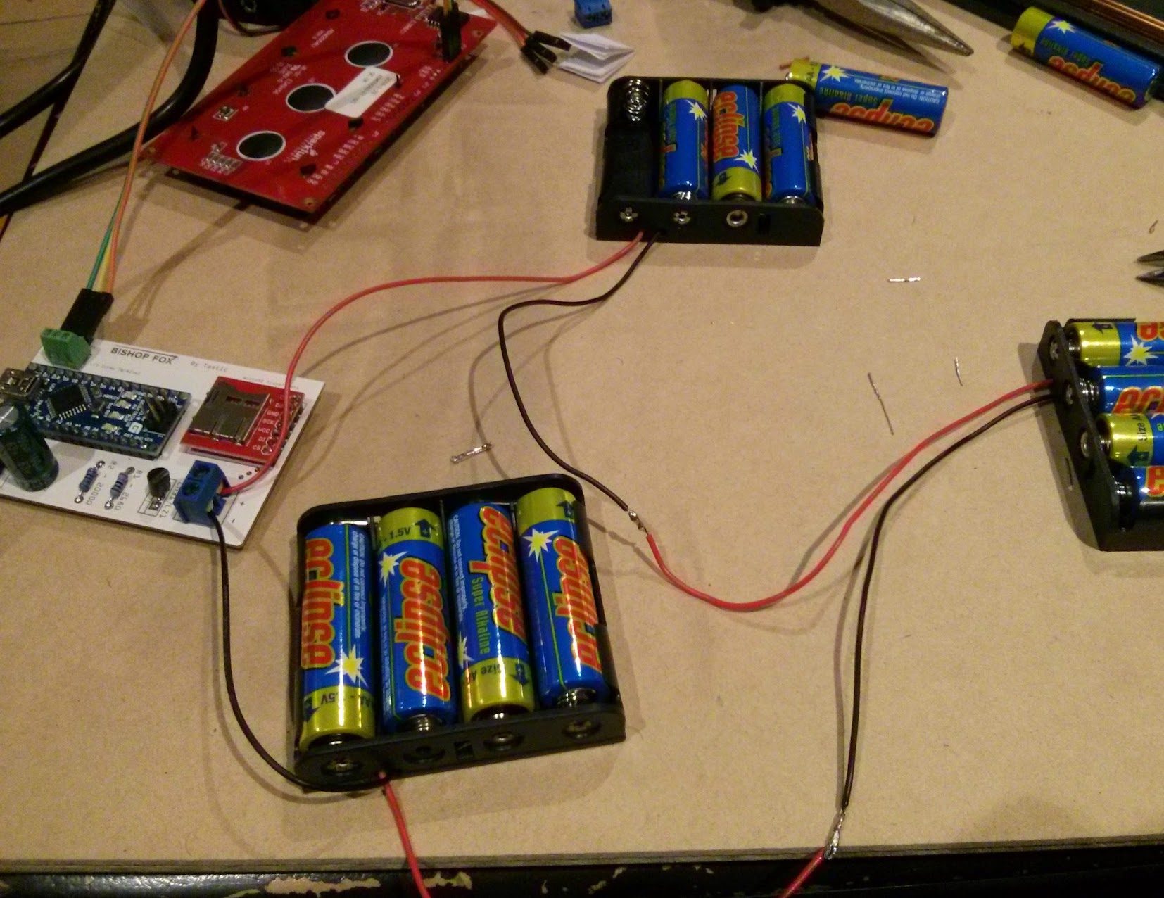
In the image above, you may notice the lack of a switch in between the last battery back and the terminal block on the PCB. When building the RFID tastic, my friend and I added the switch later, after confirming that the battery circuit was working fine.
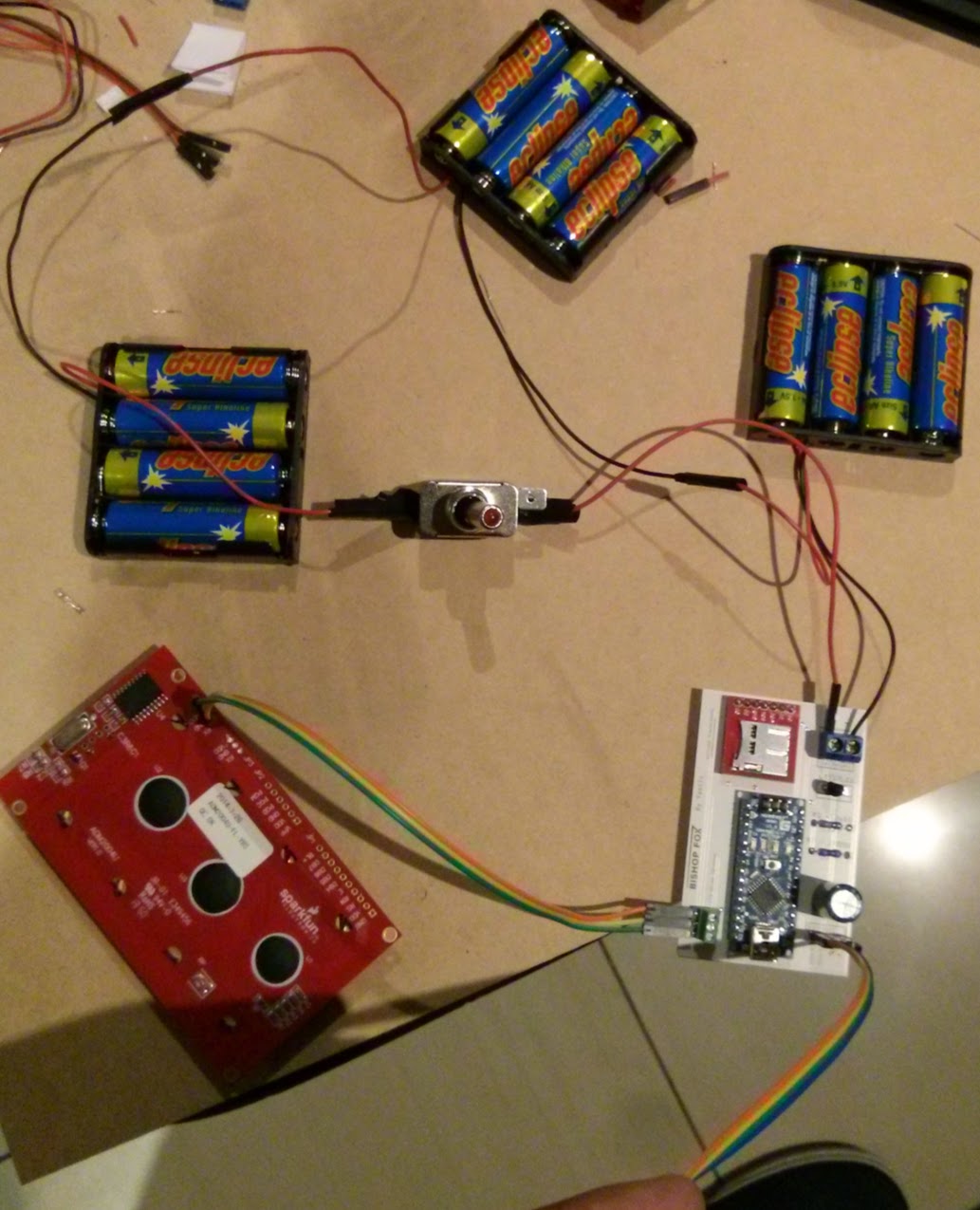
The entire circuit is below (without the RFID reader connected):
5. Connect the PCB to the HID Maxiprox
By using the header pins we put into the PCB earlier, we can easily make a connection from the PCB to the reader. The photo below, shows how it could be done (colour coding to help you out):
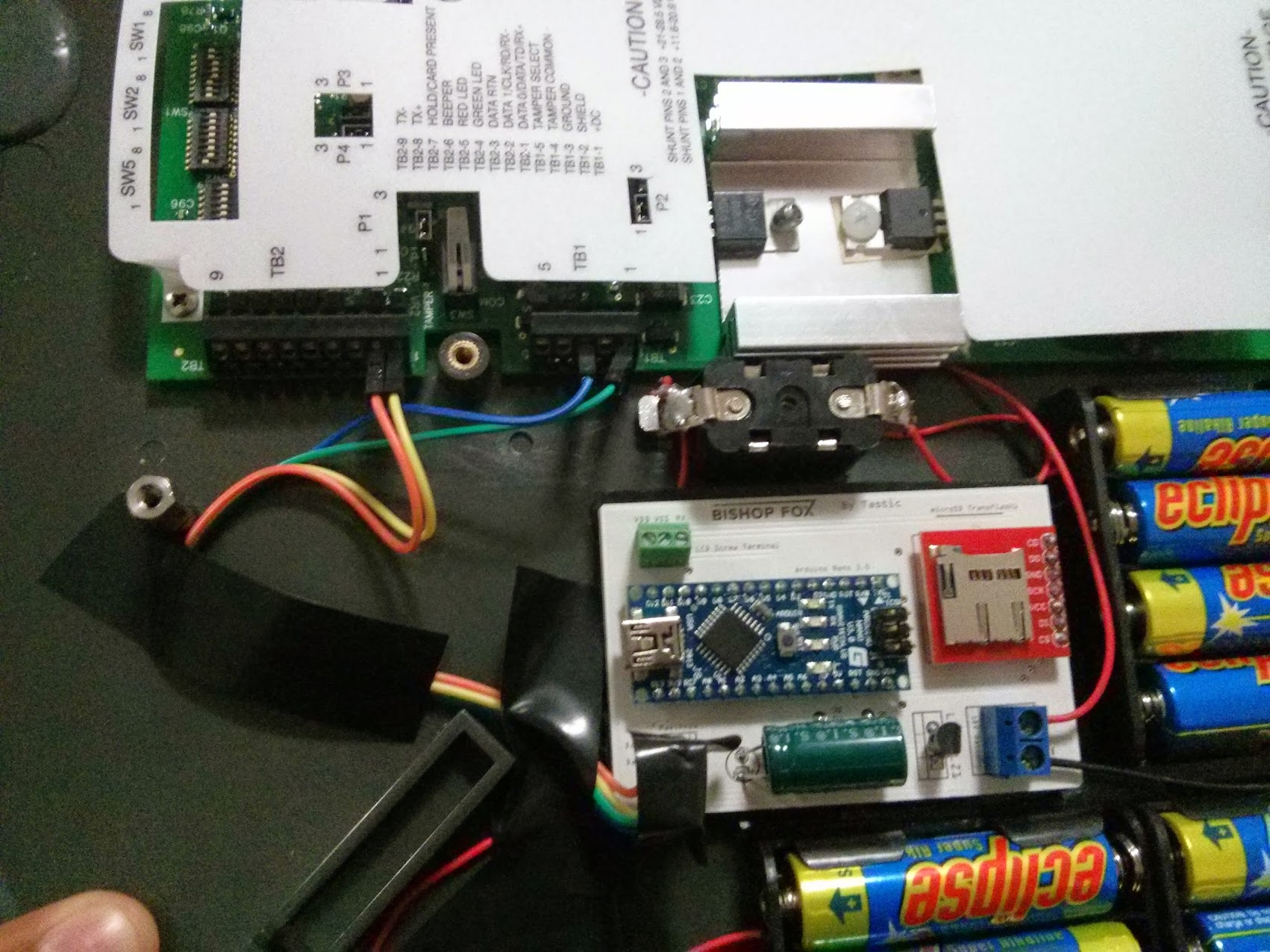
You may notice that I have not connected the wires for the LCD, this was because for some reason it was somehow shorting the entire circuit. I concluded that it was either faulty, or that I had messed up something with the power distribution, however as soon as it was removed, everything was working fine, consistently.
6. Finishing Up With Hardware
To finish up the project, simply hold everything down with electrical tape. To make sure that the PCB does not move around when the Tastic is closed, you can use double sided tape or something similar.
One of the biggest issues included making sure that the height of everything placed inside of the maxiprox was less than the actual height of the maxiprox. If anything were higher, then the casing would not close without extra pressure (which is seriously not recommended).
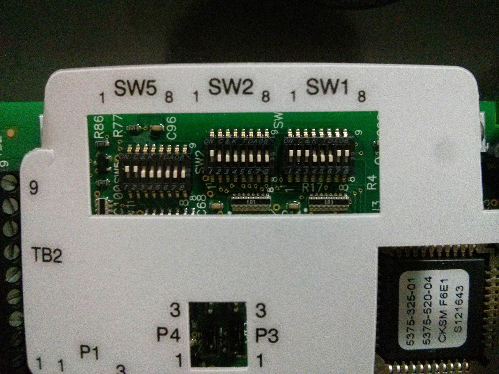
Additionally, you may need to set your Maxiprox to the following settings in the image below:
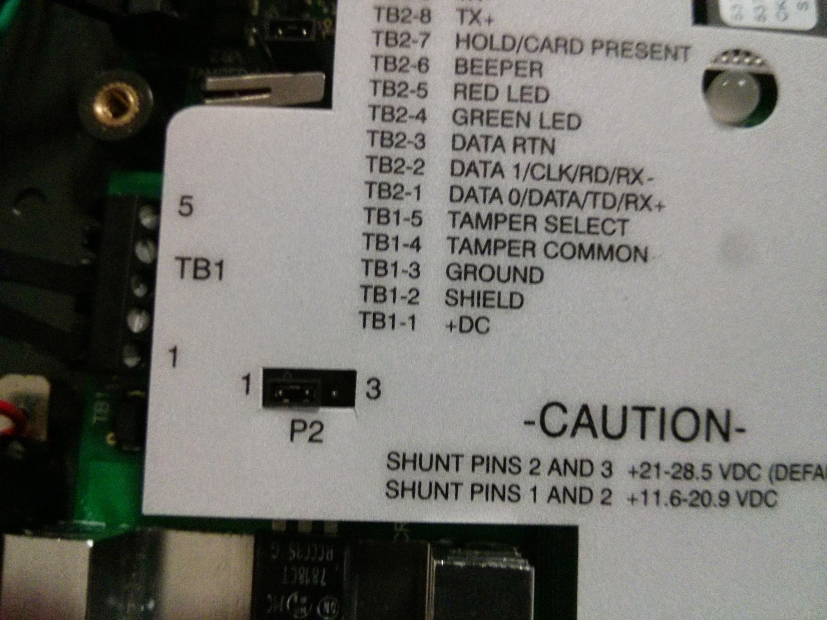
and the voltage level to the following setting:
Even though I don't have any photos of setting it up, in the finalisation stages, it's also recommended to fix the missle switch/regular switch into the hole provided in the Maxiprox.
The final version of the Tastic RFID Theif looked something like this:
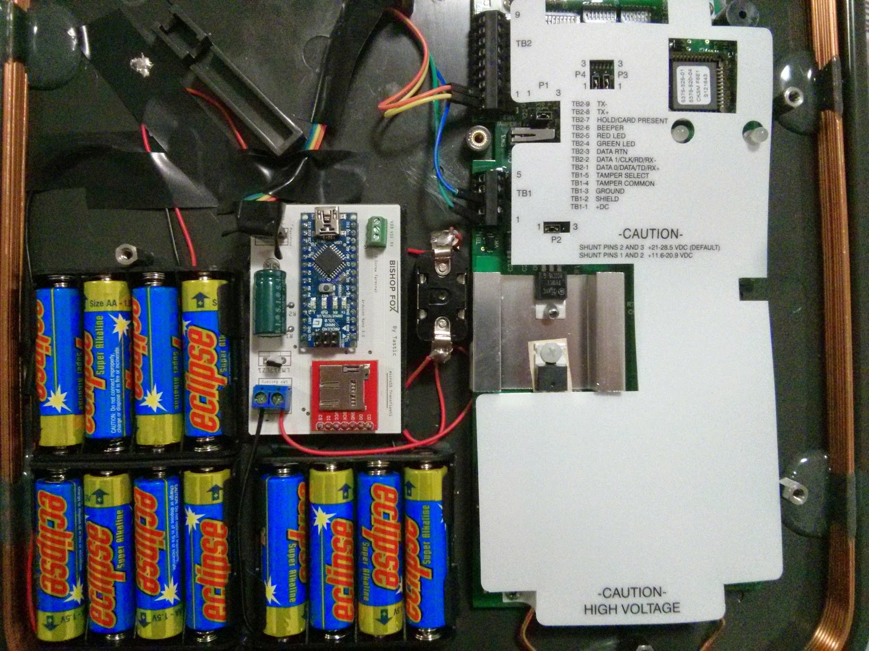
Notice the missile switch to the right of the PCB.
7. Uploading Code to the Arduino
This part is quite simple.
- Download the Ardunio software here: http://arduino.cc/en/main/software
- Download the Tastic RFID source code here: http://www.bishopfox.com/download/814/
- Download the SDFat Library for Arduino here: http://sdfatlib.googlecode.com/files/sdfatlib20111205.zip
- Read the following guide to help install the SDFat Library: http://arduino.cc/en/Guide/Libraries
- Compile the project to ensure no errors arise, and then simply connect the arduino on the PCB to your computer via a mini USB cable
- Select your respective device and COM port from the options of the Arduino IDE and click the upload button
Completion!
Once the code is uploaded, put in the microSD card into the microSD card reader on the PCB, ensure that no connections are damaged or missing and keep an eye out on the LCD screen (if one is attached).
The building process is now complete. Feel free to flick the switch on and make sure that your RFID cards are being read and written to the microSD card.
I really do recommend reading Bishop Fox's page on the tastic, and watching their video demonstrations to give you even more of an understanding of how the tastic works and how to build it.
Good luck and feel free to contact me along the way!
For near instant help, just tweet @infosec_au, otherwise, feel free to leave a comment and I'll reply when I can.
Thanks to Daniel Castillo for his help in building the RFID Tastic.